
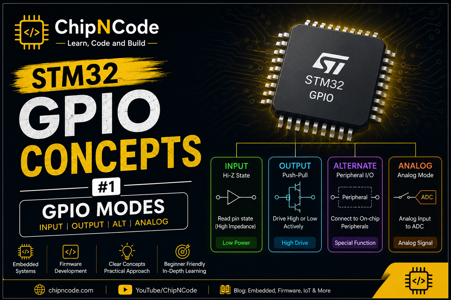
GPIO’s in the Microcontroller are usually aligned with ports. Such as PORTA, PORTB … PORTn and so on.
Each Ports has multiple GPIO Pins available depending on the microcontroller and architecture used.
How GPIO Implemented in the Microcontroller
There will be two (2) buffers.
- Input buffer
- Used to read the state of the pin
- Output Buffer
- Used to apply high or low to the enable pin
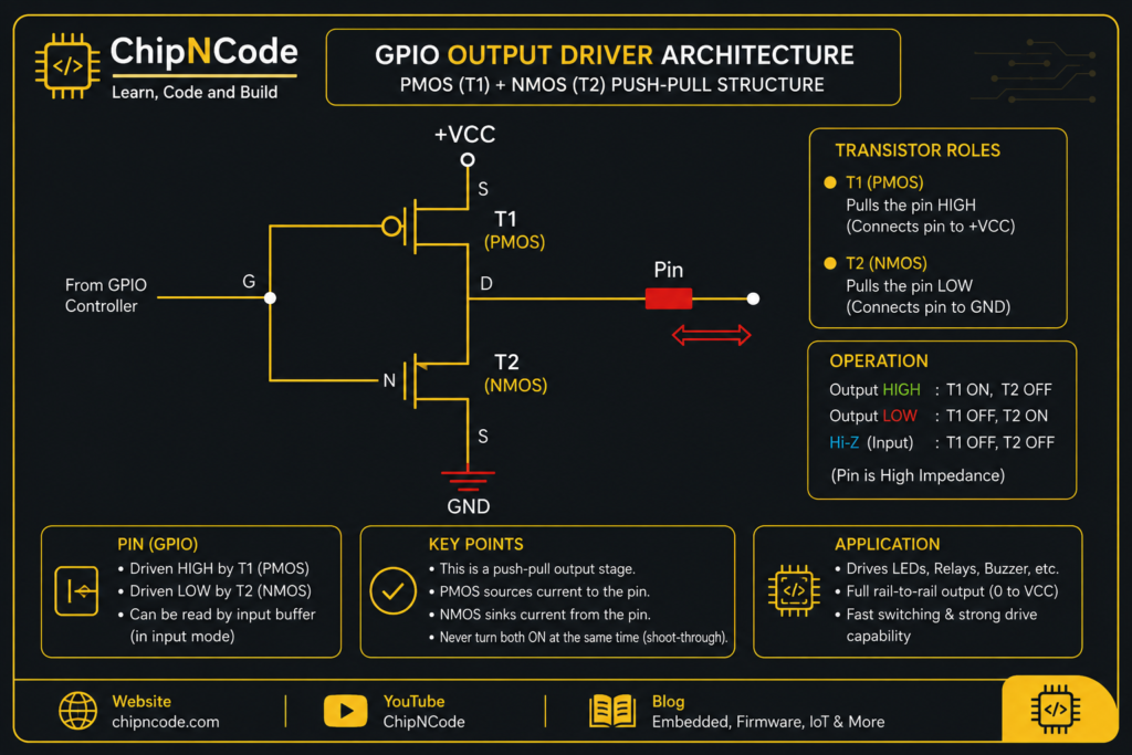
Every GPIO pin contains a pair of transistors:
- PMOS (Top transistor)
- NMOS (Bottom transistor)
Together called a CMOS Push-Pull Output
        VCC
         |
      PMOS
         |
GPIO -----+-------> Pin
         |
      NMOS
         |
GND- Output HIGH: PMOS=ON, NMOS=OFF
- Output LOW: PMOS=OFF, NMOS=ON
- Input Mode (Hi-Z): PMOS and NMOS Neither drives both OFF
- Internal Pull-Up:
           VCC
            |
      Weak PMOS / Resistor
            |
Pin --------+
            |
     Input Buffer
5. Internal Pull-Down
Pin --------+
            |
 Weak NMOS / Resistor
            |
           GND
Input Mode with High Impedance State
High Impendence is also called HI-Z State.
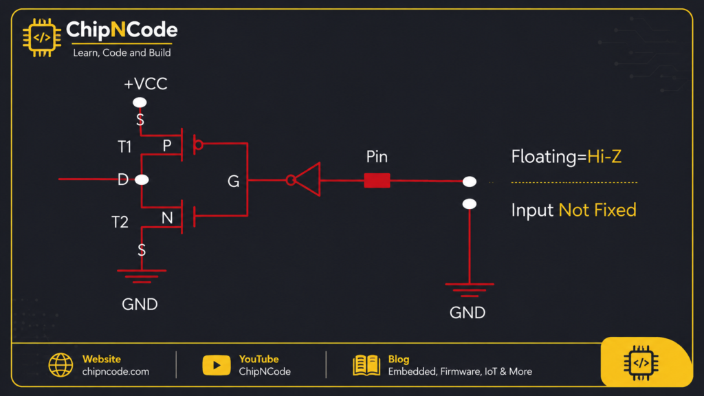
- After Powering up the Microcontroller by default all the GPIO’s will be in Either Floating state or High Impedance state.
- Keeping a pin in floating state, can lead to leakage current which may cause higher power consumption.
- This is because a floating pin is highly susceptible or sensitive in picking up the noise which may result in leakage current.
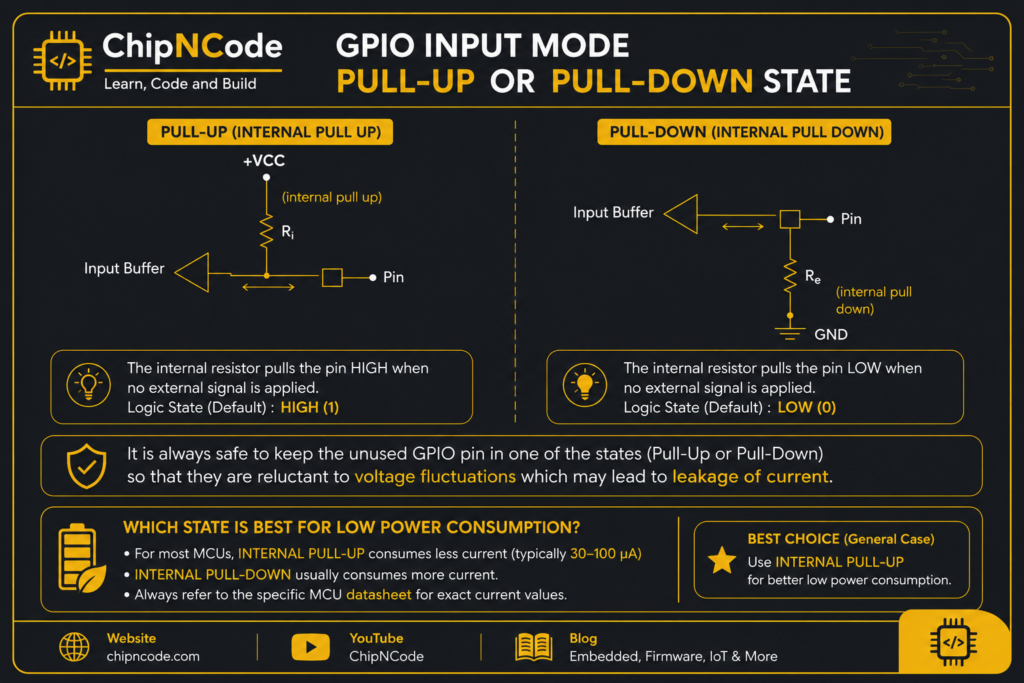
GPIO Input modes
In GPIO Input modes, we can select either
- Pull Up
- Pull Down
GPIO Output Modes
Default, When GPIO is enabled then It will be in Input mode. And In Default if PIN is configured as Ouput mode then default output mode will be Push-Pull Configuration. If we need open-drain we have to select further to choose open drain state.
Outputs can be controlled via Two transistors PMOS and NMOS to control the state
In Open-Drain Configuration Output can be only pulled to LOW not HIGH, Needed a pull-up resistor to make the OUTPUT HIGH
GPIO Output mode with Open Drain State.
Output mode with open-drain configuration is nothing but the top PMOS transistor simply not present.
When the transistor is switched ON, the output will be pulled to LOW.
when the transistor is switched OFF, the output will be floating.
- That’s the reason it is called open-drain. And in open-drain can only pull down the pin but it can’t pull up the pin.
- It can be either pull-down or float
- Open drain will be useful when we make the pull-up capabilities
Open-Drain with Pull-Up State.
- Either Internally used resistor configuration -or- using external resistor to pull-up the GPIO’s.
Example usage of Open-Drain Config
- Driving a LED using Open-Drain
- When the LED is connected to the GPIO, then default it is connected with Resistor to VCC and when GPIO is HIGH LED will be turned ON. And Resistor value mostly with 10ohm to 50ohm.
- If GPIO is LOW, then using open-drain concept. It will be grounded then LED is turned
- I2C Bus pins are configured as Open-Drain state
GPIO Optimizing Power Consumption
- If PMOS is Enabled with Pull-Up
- In this case, NMOS is disabled, so current from VCC never reaches to Ground so that leakage current won’t. Because there is no path to flow current to reach ground
- If NMOS is Enabled with Pull-Down
- In this case, There is VCC completely disabled, there is no current to flow from source.
- If it’s floating state: Leakage possibility
- small amount of current sink from VCC to Ground
- indeterminate voltage level turns ON both the transistors with “Resistance” this cause current flow